The US military work and deploy in some of the planet's most demanding and harsh environments, as well as space. The equipment and hardware employed by the armed forces must be able to handle those rigors; otherwise, failure of that equipment is almost a certainty. Vibration, extreme temperatures, water, dust, pressure, and shock are some potential impacts that can render equipment and hardware inoperative. To that end, the military has adopted MIL-STDs (Military Standards) by the US Department of Defense (DoD) to ensure hardware is manufactured within specific requirements to handle the elements.
The MIL-STD defense standards were established after WWII to provide uniform requirements and ensure interoperability for the military and its secondary industries, which focuses on engineering and technical requirements, processes, procedures, practices, and methods. Those standards are still in use today and encompass five types of defense standards:
- Interface requirements
- Design criteria
- Manufacturing processes
- Standard practices
- Test methods
In this article, we'll focus on the MIL-STD-202, which falls in the test methods category and is commonly used to evaluate RF connectors for defense and other harsh environment applications.
What is MIL-STD-202?
MIL-STD-202 establishes a series of tests methods to assess the ability of electronic components to withstand the harsh environmental, mechanical, and electrical conditions encountered in military applications. It determines the reliability, durability, and performance under the operational and environmental conditions encountered during service life.

Figure 1: The standard covers small components, less than 300 lbs, or a test voltage less than 50kV rms.
Components that fall within the scope of the standard include capacitors, connectors, resistors, switches, relays, and other small components. In this standard, small means under 300 pounds or with a root-mean-square (RMS) test voltage under 50 kV.
The Purpose of Test Methods
The test methods are designed to serve three general purposes. The first is to define test conditions that reflect real-world conditions and can be reliably reproduced. However, the standard makes clear that it is not possible and not expected for the tests to match service conditions exactly. Exact conditions can only be obtained in the field.
Next, the standard is meant to consolidate the test methods that are similar in character and appear in a variety of specifications, into a single standard. This allows for them to be kept uniform, which has the added benefits of reducing the number of resources required for testing. To achieve this, the test methods are made as generally applicable as possible.
Finally, the standard is meant to provide test methods for parts that are not already covered by another military specification. The military has several specifications and test methods for specific standardized components. However, there are still many components that don’t have a unique specification to look to when it comes to testing and instead turn to MIL-STD-202.
Test Classes and Revisions
The MIL-STD-202 standard features several tests that can be carried out for specific electronics and other components, which are designated under a numbering system. These include three classes of tests: environmental (methods 101 – 199), physical (methods 201 – 299), and electrical (methods 301-399).

Figure 2: Test methods are divided into three classes – environmental, physical, and electrical.
Within each class, test methods are serially numbered in the order in which they are introduced into this standard.
They also include revisions of test methods, which are indicated by a letter following the method number. For example, the original number assigned to the moisture resistance test method is 106; the first revision of that method is 106A, the second revision 106B, and so on.
Testing Sequence
Recommendations are given for the sequence in which test are conducted, as shown in Table 1. Mechanical and thermal stressing should be done prior to moisture resistance testing according to this philosophy.
| Group I (all samples) | Group IIa (part of a sample) | Group IIb (part of a sample) | Group III (all units that passed group II tests) |
| Visual inspection | Shock | Resistance to soldering heat | Moisture resistance or seal test on hermetically sealed parts |
| Mechanical inspection | Acceleration | Terminal strength | |
| Electrical measurements | Vibration | Terminal shock | |
| Hermetic seal test (if applicable) |
Table 1: Sequence and groupings of tests.
Test Methods for RF Connectors
To see how these test methods are applied we will look at the performance specification for a group of RF connectors. MIL-PRF-39012 defines the performance specification of coaxial RF connectors and references the following test methods from MIL-STD-202:
- Test method 101: Salt Atmosphere (Corrosion)
- Test method 106: Moisture resistance
- Test method 107: Thermal shock
- Test method 204: Vibration high frequency
- Test method 213: Mechanical shock
- Test method 301: Dielectric withstand
- Test method 302: Insulation resistance

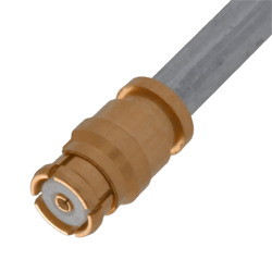
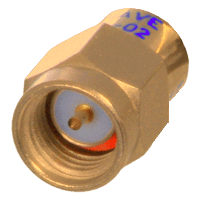
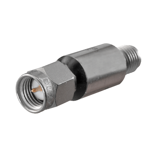
Figure 3: Example RF connectors covered by MIL-PRF-39012: SMA (left), Type-N (center), SMC (right)
Test Method 101: Salt Atmosphere (Corrosion)
Test Method 101, which is titled Salt Atmosphere (Corrosion), was originally intended to test components in in conditions that mimic a sea or coastal environment. The test was found to be insufficient for this task, however it has found use for testing the uniformity of protective coatings and comparing test lots.
Test Method 106: Moisture Resistance
Moisture is a common threat to electronic components used in the field, especially in tropical environments. Test method 106 is intended to evaluate components for their resistance to moisture and the negative effects that occur over time in hot and humid environments. These can include physical material defects such as corrosion, physical distortion, breakdown of organic material, the leaching of materials, or even electrical performance degradation.
Test Method 107: Thermal Shock
Test Method 107 is a specific test designed to evaluate the ability of electronics and electronic components to withstand thermal shock. Thermal shock refers to the rapid change in temperatures that a component may experience during operation or when exposed to specific environmental conditions. This can impact RF connectors, which can crack, warp, or damage the termination and render the device inoperable.
During the thermal shock tests, the component is monitored for any physical or electrical damage, such as cracks, fractures, delamination, electrical resistance changes, or other abnormalities. Specific requirements can change depending on the component type, application, and customer needs.
Test Method 204: Vibration, High Frequency
Test Method 204, subject’s components to vibration to determine the effect this has on performance and reliability. Military applications, such as aircraft, missiles, and mobile ground units can experience many types and frequencies of vibration during operation. A range of specific test conditions exist and are selected based on what the intended application conditions are expected to be.
Test Method 213: Mechanical Shock (Specified Pulse)
MIL-STD-202, Method 213, is used to evaluate the ability of electrical and electronic components to withstand mechanical shock. Mechanical shock can damage or compromise RF connectors during handling, transportation, or operational conditions in harsh environments. The tests involve subjecting components to a series of single shocks of a specified magnitude.
Test Method 301: Dielectric Withstand
Test Method 301 applies a high voltage to electronic components to assess their ability to withstand and operate under elevated electrical stress without failure. This test is crucial for ensuring the reliability and safety of military equipment, as it can reveal insulation weaknesses and potential for electrical breakdowns in harsh environments. Various test conditions are tailored to mimic the electrical stresses components might face in actual service, including sudden voltage spikes and prolonged high voltage conditions.
Test Method 302: Insulation Resistance
Test Method 302 measures the resistance offered by a component's insulation material to the flow of electric current. This test is essential for evaluating the insulation effectiveness in preventing unwanted current flow that can lead to electrical shorts and circuit failures. The test is particularly vital for military applications, where electronic systems are exposed to extreme environmental conditions that could compromise insulation integrity. Specific test parameters are chosen based on the operational environment expected, ensuring that components maintain their performance and reliability under all conditions.
Leveraging Industry Experience
These are just a few examples of the MIL-STD-202 standard that tests electronic and electrical components in harsh environments and hazardous conditions. The entire list of MIL-STD standards is exhausting and, at one point, consisted of over 45,000 listings across a multitude of test procedures and methods. This is, of course, to provide a detailed overview of how components and equipment are validated and to ensure operation in many environments without fail.
Cinch professionals are available to help with questions you may have about how these standards might impact your choice of components and how to best determine what your operation will need.

 127-0693-001
 M39030/3-11N
 M3933/14-01N